- Author Maria Gibbs gibbs@autolifeadvice.com.
- Public 2023-12-16 03:05.
- Last modified 2025-01-22 17:47.
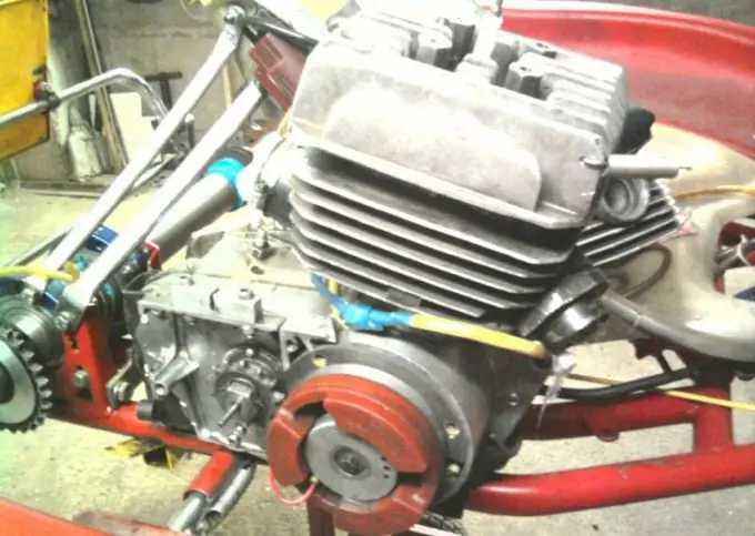
The engine of the Minsk motorcycle is notable for its availability for self-boosting. At the same time, it not only increases the power up to 15 hp, but also becomes more economical, and with the thoroughness of the work, it also becomes more durable.

Instructions
Step 1
Decide on the condition of the engine. The ideal option would be a new and run-in one. If the original motor is old, get a new crankshaft, piston with rings, bearings, seals and tune in to the painstaking work. First of all, completely disassemble the power unit into its components.
Step 2
Achieve the alignment of the windows in the liner with the channels in the cylinder jacket by metal stripping. At the same time, make sure that the thickness of the walls of the jacket and the neck of the crankcase remains at least 3 mm. To process canals, use a drill with a set of cutters and scrapers. Achieve symmetry and cleanliness of the surface of the purge passages. If, after processing, the surface of the channels becomes smooth in appearance and to the touch, it is not necessary to polish it. Be sure to keep the height of the upper bypass ports and the vertical blowdown angle unchanged. Make the leading edge of the bypass window sharp, and saw off the upper and lower edges of the upper purge window along a radius equal to the thickness of the sleeve.
Step 3
Check that the cylinder skirt fits freely into the crankcase assembled without a gasket. If necessary, remove excess metal from the crankcase throat. Adjust the bypass passages between the jacket and the crankcase in a pattern that follows the contour of the jacket bypass passages. The liner skirt must not block the bypass channels. If there is an overlap, remove the lintel and adjust the liner windows to match the crankcase windows. Rebore the intake port so that there is a smooth and stepless transition from a round diffuser to a rectangular one, with rounded curves to the exhaust port.
Step 4
Align the outlet duct well and be sure to polish it. File the top and bottom edges of the window into an oval shape. Chamfer the outlet and upper bypass ports. Also chamfer the piston rings and cover the rings with matte chrome. File the gap in the ring lock to 0.2-0.3 mm. Finish the surface of the cylinder liner by grinding, honing or lapping. Bring the gap between the piston skirt and the cylinder bore to 0.04-0.05 mm.
Step 5
Treat the piston skirt windows to match the liner skirt windows. Round off the edges on the piston skirt with a radius of 0.5 mm. Polish the piston skirt itself. At bottom dead center, the piston must not cover the lower edge of the upper bypass port. To do this, either remove the flats, or grind the piston head along a radius of 70 mm to the required amount. Leave the bottom of the piston no thinner than 5 mm. Mill the ends of the connecting rod bosses so that their dimensions do not differ by more than 0.1 mm. Lighten the piston pin with a groove under the cone, protecting its working surface from damage.
Step 6
Check the radial clearances in the upper and lower connecting rod bearings. They should be no more than 8 microns (top) and 12 microns (bottom). If the clearances are greater than these values, replace the crankshaft with a new one. Press out the crankshaft fingers separately from each cheek. Plug the standard balancing holes with aluminum, and compensate for its weight with lead plugs inserted into the lower parts of the crankshaft cheeks. Grind the cheeks themselves to a diameter of 100 mm, avoiding damage to the pins. Reduce the diameter of the pins themselves to 17 mm using fine sanding paper.
Step 7
Achieve a smooth mating of all surfaces of the connecting rod, avoiding risks at the mates. Be sure to polish the outer surface of the connecting rod. Before assembling the crankshaft, rub all parts of the lower connecting rod bearing with molybdenum disulfide. Press the crank pin without distortions. In this case, the axial clearance between the lower head of the connecting rod and the cheek should be 1, 6-1, 7 mm. Center and balance the crankshaft carefully.
Step 8
Bore the surface of the crankcase crankcase clean. Secure the aluminum rings with epoxy glue and 3 M5 countersunk screws. Fill all gaps in the crankcase with epoxy resin filled with aluminum powder or plasticizer. After processing, assemble the crankcase with sealant without gasket. When installing the crankshaft, secure it against longitudinal displacements with two washers. Assemble all engine threads using an anaerobic sealant.


