- Author Maria Gibbs [email protected].
- Public 2024-01-09 07:02.
- Last modified 2025-01-22 17:48.
An important element of a mechanical transmission is the clutch, which is used to momentarily disconnect the engine from the transmission. In addition, the clutch is a kind of damper that protects the engine from overload.

Invention of the clutch mechanism
The invention of the clutch mechanism is attributed to Karl Benz. Whether this is so or not, it is impossible to establish reliably: several companies were simultaneously engaged in the production and improvement of the first cars in the 19th century, and all of them followed their development, as they say, "head to head." The oldest type of clutch, widespread on most cars of the late 19th and early 20th centuries, was the conical clutch. Its friction surfaces were tapered. Such a clutch transmitted more torque, with the same dimensions, in comparison with the current single-disc one, it was extremely simple in its structure and in its care.
A heavy tapered disc of this type of clutch possessed great inertia, and when shifting gears after depressing the pedal, it still continued to rotate at idle, which made shifting the gear into a difficult operation. To brake the clutch disc, a special unit was used - a clutch brake, but its use was only half of the solution to the problem, as was the replacement of one cone with two less massive ones. As a result, already in the 1920s, such a heavy and cumbersome (for whom it requires significant muscular effort to use) construction, like a conical clutch, was completely abandoned. There was also a reverse cone clutch that worked to expand.
The very principle of this mechanism has found a new embodiment in the design of modern gearboxes with synchronizers. Gearbox synchronizers are essentially small conical clutches that work by rubbing bronze (or other high-friction metal) against steel.

The principle of the mechanism
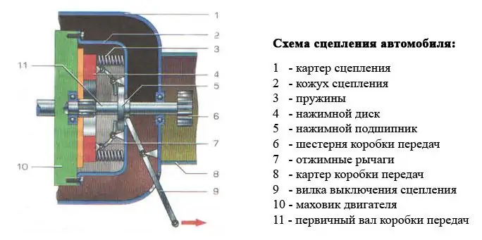
The following main parts are involved in the operation of the clutch assembly:
- a flywheel rigidly attached to the crankshaft of the power unit;
- 2 discs - pressure and driven, which make up the friction mechanism;
- casing;
- pressure springs;
- bearing;
- diaphragm spring in the form of concentric levers;
- fork;
- hydraulic actuator slave cylinder that is actuated when the pedal is depressed.

The most primitive mechanism that was used in the last century did not include a hydraulic cylinder, which greatly facilitates the work of the driver. Instead, there was a mechanical cable drive.
The drive disc (aka the basket) is bolted to the flywheel and rotates with it. The normal state of the clutch when the pedal is in the depressed position is “connected”. That is, the crankshaft of the motor and the primary gearbox are connected by means of a disk pressed against the plane of the flywheel by a spring.
When you press the pedal, the unit works according to the following algorithm:
- Through the brake fluid, the force is transmitted to the hydraulic cylinder that pushes the fork.
- The fork presses on the bearing, and it pushes the concentric levers, whose ends abut the pressure plate.
- The ends of the levers are pulled back and release the disc, as a result, the connection between the shafts is broken, while the rotating crankshaft does not turn the gears of the box.
- When you need to drive away, you gradually release the pedal. The bearing releases the levers, which, under the influence of the springs, press on the disc. The latter is pressed against the flywheel by the friction surface and the car moves smoothly forward.
- The algorithm is repeated with each gear change.
Varieties of knots
Existing clutch designs are divided into the following types:
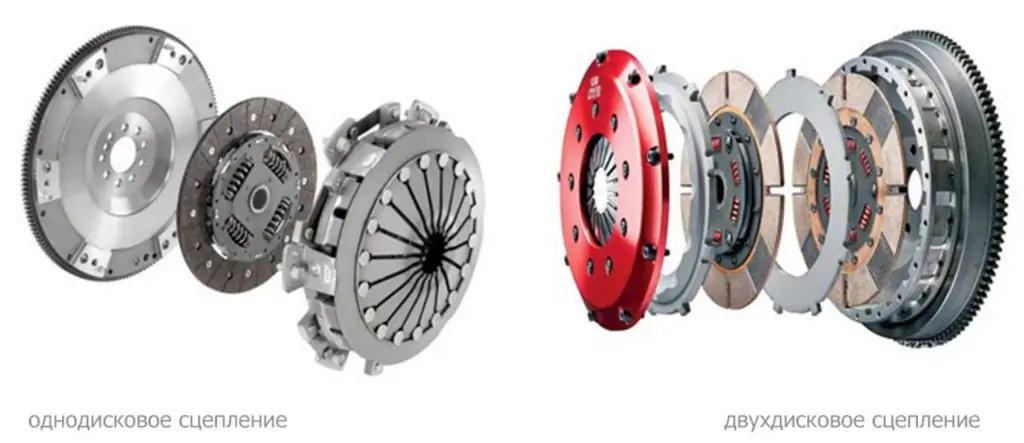
- by the number of friction surfaces: single- and multi-disc;
- by control method: mechanical, servo-driven and hydraulic;
- working environment - dry and wet.
The multi-disc system is implemented together with high-powered motors. The reason is as follows: one group of friction linings is hard to bear increased loads and wears out rather quickly. Thanks to the design with two discs separated by a spacer, the large torque is evenly distributed over the 2 groups of pads (squeezing occurs simultaneously). Reducing the specific load gives an increase in the service life of the unit.

Mechanical
The structure of a mechanical clutch is usually one or more friction discs that are compressed with the flywheel or between themselves by springs. The mechanical clutch is driven by means of a cable.
The flywheel is bolted to the engine crankshaft. It is used as a master drive.
It is now common to use a dual-mass flywheel that stabilizes torque loads on the shaft. Both parts of it are connected to one another by springs.
The basket is of a pressure type (the petals move inward, towards the flywheel) and an exhaust type (for example, on some French models). Each type has its own release bearing. The basket is bolted to the flywheel.
The driven disc enters the splines of the box shaft and is able to move along them. Disc damper springs perform the function of smoothing vibrations at the time of gear shifting.
Friction pads are riveted to the base of the driven disc. They are made of a composite material: more often - from Kevlar threads or carbon fiber, sometimes - from ceramics. Particularly durable are the cermet linings. They are designed to withstand temperatures up to 600 ° C for a short time.
The release bearing is fixed to the protective casing and has a release pad. Located on the input shaft.
Principle of operation
A flywheel is attached to the engine crankshaft and acts as a drive disc. In addition, there is a "basket" (ie pressure plate) and a clutch disc (with friction linings). The "basket" presses the driven disc against the flywheel, which contributes to the transmission of torque to the gearbox from the motor.
The pressure plate has a circular shape with a radial base and is tightly connected to the flywheel. It contains petal-type release springs that interact with the pressure pad. The size of the pad corresponds to the diameter of the flywheel. A driven disc is located between the platform and the flywheel. The release bearing presses the release springs in the center of the release disc. The movement from pressing on the clutch pedal passes through the cable further to the release fork, and it already displaces the release bearing. In the center of the disc, the bearing presses against the release springs. As a result, the platform comes out of engagement with the driven disc.
Hydraulic
A hydraulic clutch is a hydraulically operated mechanical clutch.
The main components are, first of all, cylinders: main and working. If the clutch pedal is depressed, then the rod of the main hydraulic cylinder will move accordingly. The resulting pressure passes through the tube into the slave cylinder, which moves the release fork, and that displaces the bearing.
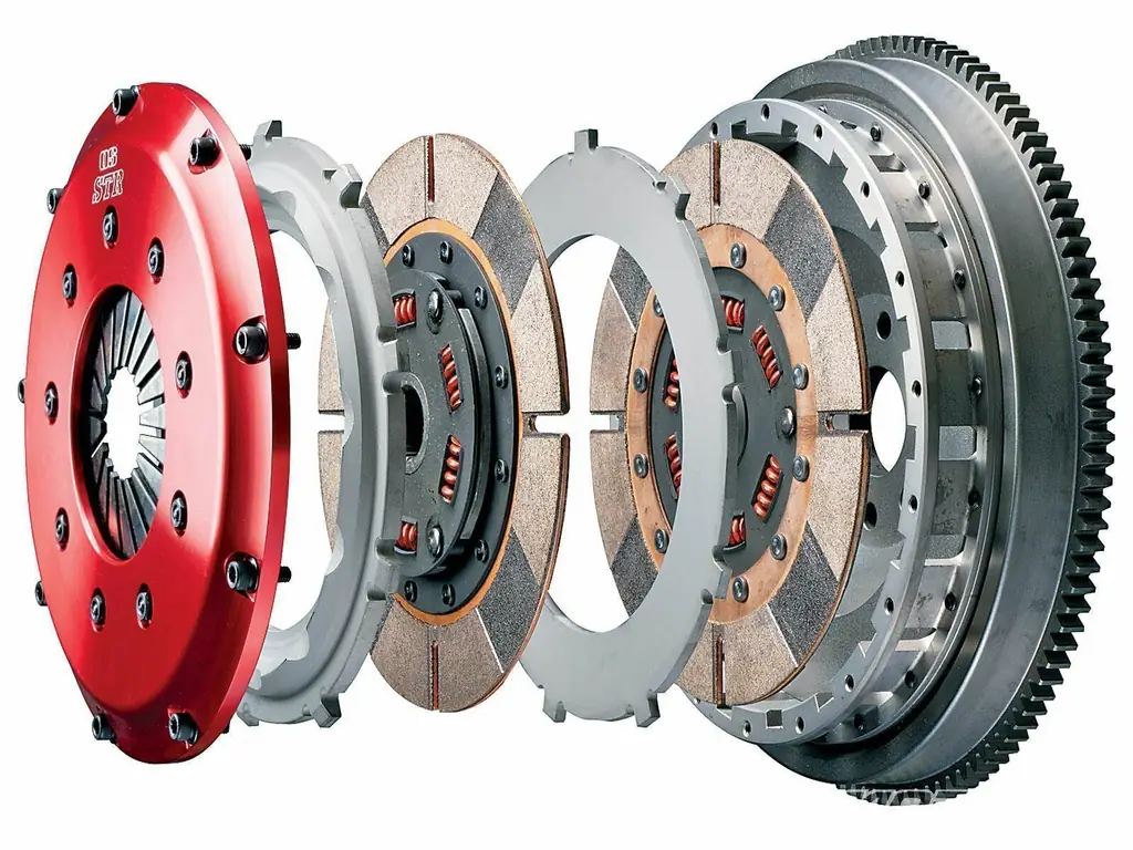
Two-disk
This clutch is used in heavy trucks, tractors, tanks, some motorcycles and sports cars.
It is used when over-powered torques are present. Its installation provides a longer service life of the used structural parts.
It uses 2 driven discs, and the "basket" has two working surfaces. A synchronous pressing control system has been added to the design.
Wet friction
The mechanisms of this clutch perform their functions in an oil environment.
It is used on motorcycles that have a transverse motor.
This is due to the design feature of the motorcycle engines themselves. Here, the same crankcase is used: for both the gearbox and the motor.
Principle of operation. The stem, which is passed through the hollow shaft of the gearbox, sends out a reciprocating motion from the clutch lever cable.
The role of the release bearing is played by the ball at the end of the rod. It acts on the fungus. As a result, the pressure plate is retracted, the compression between the disc pack is weakened, the gearbox shaft stops turning.
Electrical
The constructive difference between the electrical system and the mechanical one is the electric motor. It turns on when the clutch pedal is moved down. The electric motor moves the cable, and it already displaces the release bearing through the rocker arm.
Common malfunctions
Most often, the following problems occur in the clutch mechanism:
- leakage of the cuff of the hydraulic cylinder;
- critical wear of friction linings;
- weakening of the diaphragm spring;
- oiling and slipping of the driven disk;
- breakage or jamming of the plug.
Only the first malfunction associated with a brake fluid leak allows you to get to the car service without any problems. In other cases, the clutch may not engage and you will not be able to drive further.


