- Author Maria Gibbs [email protected].
- Public 2023-12-16 03:05.
- Last modified 2025-01-22 17:48.
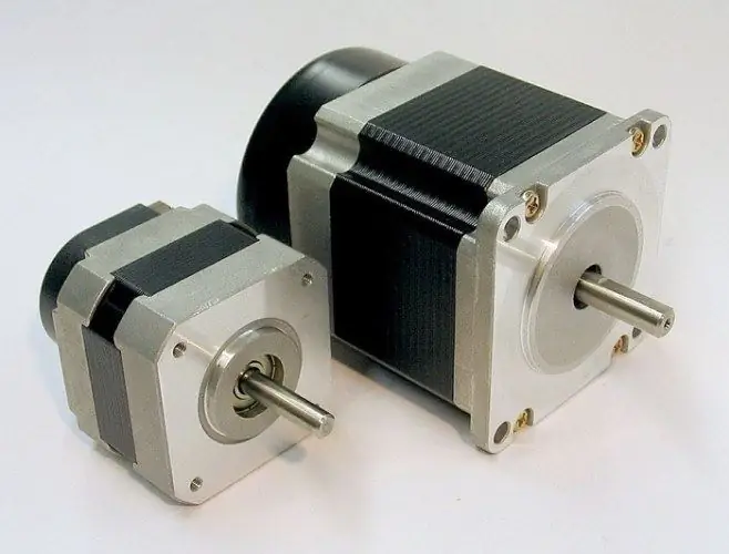
The stepper motor is becoming an increasingly popular actuator used in a wide variety of technical fields, including electronic devices and control circuits. Having the ability to accurately position the shaft in a certain position, such an engine can be used, for example, to control an additional fan located in the passenger compartment.

Necessary
- - drive motor of the head from a floppy drive;
- - microcircuit ULN2003A;
- - PIC16F84 processor;
- - connecting wires.
Instructions
Step 1
Use a read-write head drive device from a 5.25-inch floppy drive, for example, TEAC brand, to manufacture a stepper motor. It is a five-terminal unipolar motor. Four pins are connected to the windings, and the fifth is common and serves to supply 12V power. The specified motor will provide a step of 1, 8 degrees, therefore, for a complete revolution of the shaft, 200 pulses will need to be applied.
Step 2
If the specified device is not available, take the motor from a more modern 3.5-inch drive. Keep in mind that such a motor is bipolar, therefore, it will require the installation of a special driver to control the system.
Step 3
Prepare the ULN2003A IC, which is a set of open collector transistors with a protective diode in the load circuit. Connect the first four leads of the motor, respectively, to the microcircuit pins marked with 14, 13, 12, 11. To connect, use a special terminal block or make a connection by soldering.
Step 4
Connect the pins of the microcircuit from the third to the sixth, respectively, to the pins of the PIC16F84 processor, which are numbered from the sixth to the ninth. Turning the stepper motor on and off will be carried out using a button connected to the MCLR and VSS pins on the processor.
Step 5
After completing the wiring, apply 12V power using the appropriate common wire coming from the motor. The program will send 200 pulses to the windings, which will provide a half or full revolution of the shaft in a pulsed mode. This is followed by a pause, after which the shaft in the same step mode turns 180 degrees in the opposite direction or makes a full turn (this is determined by the specified mode).


