- Author Maria Gibbs [email protected].
- Public 2023-12-16 03:05.
- Last modified 2025-06-01 05:12.
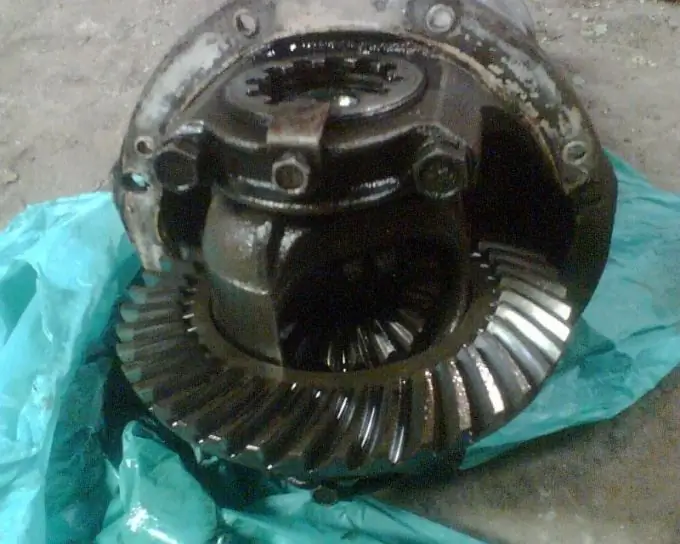
When operating a car, especially in difficult conditions and with a trailer, the rear axle gearbox gradually goes out of order. This becomes noticeable when, when driving at a speed of 30 km / h, a loud "howl" is heard from behind. The VAZ gearbox is a complex unit with very serious adjustments. Therefore, it is advisable to carry them out in a specialized workshop.

Necessary
- - torque wrench;
- - an adjusting ring;
- - strong thread.
Instructions
Step 1
Wash the gearbox parts thoroughly in kerosene and inspect. If you find a defect even in one gear tooth (seizures, chipping, risks, waves), then replace the gears. Faces should be sharp between the tops and working surfaces of the teeth. Replace the main pair at the slightest nicks or rounding. Repair minor damage with fine sandpaper and then buffing. Replace the flange nut, collar and spacer sleeve with new parts during assembly. When assembling the gearbox in the old crankcase, calculate the change in thickness of the pinion shim ring as the difference in dimensional deviations between the new and old gear. It is indicated in hundredths of a millimeter on the pinion shaft by the signs "-" and "+". For example, on the new gear - 4, and on the old 12. The difference between the two corrections is 4 - (- 12) = 16. Thus, the new shim must be 0.16 mm thinner than the old one.
Step 2
Make a fixture from the old pinion gear to more accurately determine the thickness of the adjusting ring. To do this, weld a plate 80 mm long and face it to a size of 50-0.02 mm relative to the plane for the bearing. Dimensional deviation and serial number are embossed on the tapered part. Grind the bearing seats (with fine sandpaper) to a slip fit. Press the outer rings of the rear and front bearings into the crankcase. Install the inner ring of the rear bearing on the tool and insert the tool into the crankcase. Install the inner ring of the front bearing, then the drive pinion flange and tighten the nut to a torque of 0.8-1.0 kgf.m.
Step 3
Place the crankcase in a horizontal position using a level. Lay a round flat rod in the bearing bed and measure the clearance between it and the fixture plate with a flat feeler gauge. The thickness of the adjusting ring will be equal to the difference between the deviation of the size of the new gear (taking into account the sign) and the size of the gap. For example, if the size of the gap is 2, 8 mm, and the deviation is 15, then it is necessary to put an adjusting ring with a thickness of 2, 8 - (- 0, 15) = 2, 95 mm. Install the adjusting ring onto the shaft using a piece of pipe. Insert the shaft into the crankcase. Install a new spacer sleeve, then the front bearing inner race, then the collar and pinion flange. Tighten the nut gradually with a torque wrench to a torque of 12 kgf.m.
Step 4
Determine the moment of turning the pinion shaft. To do this, wind a strong thread tightly around the neck of the flange and attach a dynamometer to it. The flange should turn evenly with a force of 7, 6-9, 5 kgf for new bearings. If not enough, tighten the flange nut. The tightening torque should not exceed 26 kgf.m. If, when turning, the force exceeds 9, 5 kgf, then disassemble the gearbox and replace the spacer sleeve.
Step 5
Install the differential housing with bearings in the crankcase and tighten the bearing cap bolts. If you find axial play in the gears of the axle shafts, install thicker new support shims during assembly. The side gears should fit tightly into the differential housing, but turn by hand. Make a spanner from sheet steel (2.5-3 mm) to tighten the adjusting nuts.
Step 6
Adjust the backlash in the main pair and the preload of the differential bearings. To do this, wrap the nut on the side of the driven gear, eliminating the meshing gaps; measure the distance between the covers with a vernier caliper; screw in the second nut until it stops and pull it 1-2 teeth of the nut. In this case, the distance between the covers should become almost 0.1 mm larger; turn the first nut and set the required meshing clearance (0.08-0.13 mm). It is felt with your fingers as a backlash in engagement, while a slight knock of a tooth on a tooth is heard; Use your hand to control the constancy of the mesh in the engagement and gradually tighten both nuts until the distance between the covers increases by 0.2 mm. Turn the driven gear slowly 3 turns, at the same time feeling for play in the meshing of each pair of teeth. If it is uniform in all positions, then install the lock plates.


